Prepare Parking Specs
The Parking Specs file ParkingSpecs.TXT is part of the AFCAD 2.21 program:
Jetway Alignment Scheme
I generally group models of different airlines to align their front cabin door, respectively the 2nd door of heavies, with the jetway exit in order to achieve a visual improvement and to prevent aircraft from crashing with the wing into the jetway. I developed a scheme herefore:
     +1   753   783   788   M80a   M90ap
GATE  0   717   727   747fp 757    762c  763   300  312  321ef 380  M81p M87a DC95 M11f
     -1   738   739   747a  762afp 764a  777ft 789  319e 320ef 321p 330  340  M87p DC93 DC10
     -2   732a  733   734   737    74Lp  318e  319f F100 CRJ7  CRJ9 E145 E190
     -3   732p  735   736   747v2p 319p  322p  F28  F70  CRJ2c E135 E140 E170 B146m
     -4   B146p CRJ2p D328p
Legend :
a = Aardvark model only
c = CDAI model only
e = EvolveAI model only
f = FSP model only
g = AIG model only
m = FMAI model only
p = PAI model only
t = TFS model only
For example: if parked in a particular position, both 738 and 319e have their front cabin door at about the same position, they are grouped together therefore. Aircraft of the "GATE -2" category can also use parking spots of category "GATE -1" and upwards for example, but the nose would possibly be some meters backwards of the jetway exit. In reverse an aircraft of category "GATE -2" should not be grouped with downward category aircraft of "GATE -3" for example, the wing would get very close to the jetway or would even crash into it.
Creating Parking Specs Entries
Now I group the same models of different airlines to achieve an effective use of the mostly too few available jetway positions. Some airlines fly in with different models, thus their ICAO code appears in different code lines. In order to save jetway positions and to get more flexibility, I often also melt models of different radiuses, B777 (41m) and A340 (42m) series can be mixed very well for example, since their 2nd cabin doors have about the same positions. Sometimes I assign LCC's to ramp positions intentionally, not just regionals. Airlines with greater activities usually get their own and exclusive positions. Sometimes I either don't group them and keep them in mind for later, or I group them additionally to their exclusive positions. When compiling the parking specs entries, I follow the rules and conventions of:
- Airline Parking Coding - regional aircraft receive an "X" and cargo aircraft a "C" suffix to the ICAO code
- AI Model Radiusing - models in aircraft folder should be radiused according to the table of course
Here is an example of a complete Parking Specs entry set for WRRR Denpasar Bali:
GATE WRRR Int  0 m43 ,255,255,255,CPA,GIA,JAA,JAL,TSO
GATE WRRR Int -1 m41 ,255,255,255,CPA,SIA,THA
GATE WRRR Int -1 m40 ,255,255,255,CAL,GIA,JST,KAL,MAS,QTR
GATE WRRR Flx  0 m35 ,235,235,235,EVA,JAL,LNI,THA,TSO,UIA,WON
GATE WRRR Flx -1 m23 ,235,235,235,COA,GIA,MAS,QFA,RBA
GATE WRRR Dom -1 m23 ,215,215,215,BTV,GIA,LNI,MDL
GATE WRRR Dom -2 m23 ,215,215,215,MNA,SJY
GATE WRRR Rmp  0 m23 ,155,155,155,AXM,VLU
GATE WRRR Rmp  0 m16 ,155,155,155,ANOX,MNAX
Legend :
Int = intl. gate
Flx = gate for intl. and domestic flights
Dom = domestic gate
Rmp = ramp position
-1 m41 = jetway alignment and required radius
255,255,255 = parking spot color
I often group MD80 or B757 together with B763's and other medium aircraft, if there is few medium aircraft traffic. I found out, that it can cause problems, if I assign too many ICAO codes to one string, but up to 10 different airline codes in a single string shouldn't be a problem, however. Sometimes airline alliances use particular gates exclusively, in such cases I only add codes of member airlines that really fly in.
AFCAD Settings
- in the Tools menu go to Options
- select Metric Parking Radius
- you can change to another Lat / Long Format if necessary
Backups
Backups can save you a lot of time and tears:
- go to your AFCAD folder
- make a Copy of the AFCAD you're working on
- in order to deactivate the copy, just Change Suffix from "bgl" to "xgl"
Top-Down View Options
At many sceneries the Top-Down View lets vanish apron and even scenery objects like jetways,
if you zoom very close to your aircraft. We have another option besides the Top-Down View:
- select a small aircraft like the Lear 45
- in the Go To Airport menu select airport and Active Runway
- click Ok
- in the View Options click Spot Plane
- set Zoom to "001.00"
- set Distance to "1" ft
- set Altitude to "500" ft
- make sure the Red Pointer Line points exactly downwards; use runway heading as reference
- click Ok
- now Save Flight and name it "0", thus it will appear at the top position in the Choose A Flight menu
- you can always Zoom now, using "+" respectively "-"
- if you change the Aircraft, just repeat steps 4. to 9. after the aircraft was loaded,
save the flight, name it properly, and you'll save time by faster access later
Display Settings
- go to the Settings Display menu
- move sliders Terrain Texure Size / Terrain Detail / Scenery Complexity / Autogen Density each to full
- uncheck Ground Scenery Casts Shadows
- uncheck Aircraft Casts Shadows
Correct The Default AFCAD
Most Default MS FS AFCADs are misaligned, crooked, faulty and poor, I always spent some time to correct this therefore:
Correct Runways
- in AFCAD program click Lock The Map Location
- check the Start Location to be aligned correctly with the runway heading and center
- usually I move the center of both the Start Locations onto the Threshold Stripes
- in the Runway Properties I check that everything is correct, respectively according to my wishes
- click tab General and make sure the runway Surface is either Asphalt or Concrete,
Bitumus is unsafe for jetliners, I generally set all airport surfaces to Concrete,
it is safe for all aircraft, and the unified surface looks better
- click tab Markings, sometimes existing basic markings are not set in AFCAD, refer to Google Earth
- click tab Lights, usually I activate all Whole Runway lights and the Touchdown Zone Lights
- click tab VASI and check whether there is at least a PAPI, which is available at most commercial traffic airports
- mark the entire Runway Link (which must be a black line), set all Lines to "No Line" and deactivate all Lights
- make sure the runway taxi link Surface matches the runway surface you have selected in the Runway Properties
- align the Runway Taxi Link exactly with the runway center line, zoom in as close as necessary therefore
- move both the End Nodes of the runway taxi link to the runway threshold,
and make sure that no taxiway edge line leaves the surface at the runway-taxiway corner
Correct Taxiways
- select the first Taxiway Designator in order to highlight a taxiway and mark the entire highlighted taxi link
- in Link Properties correct Link Type if necessary, it must be "Taxiway"
- change the Surface if necessary
- change the Width if necessary, it should be at least 120ft for safe heavy operations,
refer to Google Earth , unfortunately a broad edge pavement cannot be displayed, though it is
available at most modern taxiways, which actually have a paved width of about 200ft therefore
- set the Center Line to "Solid Line"
- set Left Edge and Right Edge lines either to "Solid" at a grass rim, or to "Dashed" at an apron rim
- activate the Lights, I always omit the Center Light if the taxiway has dashed edge lines on both sides
because it runs over an apron
- click Ctrl + T in order to change to the next Taxiway Designator, mark the entire highlighted taxi link,
and repeat step 2. to 7., do so with all other taxiways
- mark and correct all misaligned Taxiways if necessary,
sometimes taxiways parallel to a runway are not really parallel in default AFCADs,
and sometimes particular segments of a taxiway have slightly different headings
- make sure your corrections don't place existing Taxiway Sings to any absurd position,
but this is not always avoidable however
- sometimes newer Taxiways are missing, refer to Google Earth , draw them with the
Create Normal Taxi Link function, name and set them up according to the steps listed above
- try to avoid making changes to existing default Taxiway Designators
Correct Aprons
- refer to Google Earth for the correct Surface of aprons if wished, and change it in the
Apron Properties menu, Concrete is a safe surface for all aircraft
- correct the alignment and heading of the Apron Rims, zoom in as close as necessary therefore
- usually I soften the Corners from pointed to round
- if you do changes to aprons make sure all Apron Light Strips are moved appropriately too,
but never ever delete Apron Light Strips, the AI traffic may not work after it anymore
Improve Taxi Surfaces
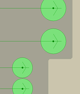
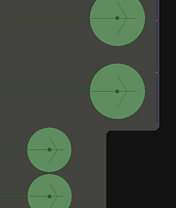
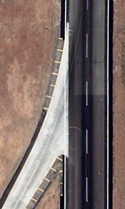
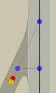
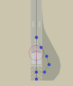
Improve Runway & Taxiway V-Turns
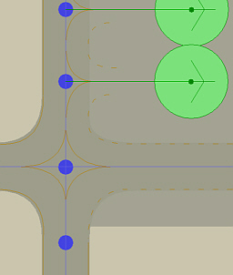
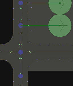
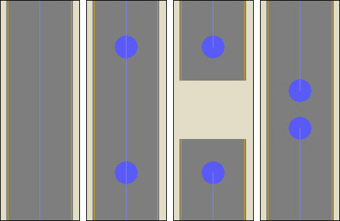
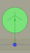
As you can see on the first and second image below, there is a difference between reality and default AFCAD. Especially AI aircraft would make odd turns when coming from south, leaving the runway for the taxiway, they might even touch the grass possibly. To improve such situations I always add a horizontal taxi link:
- use the Create Normal Taxi Link function and draw a connection link from the taxiway to the runway
inside the Hold Short Node area, you'll get a triangle
- remove the Edge Lines in the center of the triangle from both the taxiway and the new triangle link,
mark the taxiway link and open Link Properties, set either the left or the right edge line to "No Line"
and uncheck "Lights" for the same edge line, try out and make sure you take the correct edge line,
repeat the same with the triangle link, but additionally uncheck the center line "Lights" here
- use the Create Apron Polygon function and draw a triangle apron inside the taxi link triangle
in order to remove possible grass areas from the center of the triangle
- do so with all V-Turns at runway-taxiway and taxiway-taxiway connections
Improve Runway U-Turns
- use the Create Apron Taxi Link function and draw a half drop line at one side of the runway taxi link,
refer to Google Earth if necessary
- mark the Half Drop Line and open Link Properties, set all lines to "No Line" and uncheck all "Lights",
set Width to "1" ft, and select the desired Surface
- use the Create Apron Polygon function and draw a half drop surface around the half drop line,
make sure the half drop area is large enough for safe taxiing
- add an Apron Light Strip to the half drop surface rim if wished
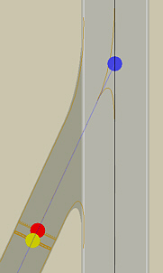
Add Missing ILS Hold Short Nodes
Often the yellow ILS Hold-Short Nodes are missing, I add them by using the Create ILS Hold-Short Nodes function, placing them partially onto the red Hold-Short Node to the heading parking and aprons direction.
Closed Taxiways
Close Taxiways Safely
ATC may let user or AI aircraft use closed taxiways, it is necessary to interrupt closed taxiways therefore.
- go to a Taxiway that must be closed by interrupting it
- put 2 Normal Nodes on the taxi link
- delete Taxi Link between the 2 normal nodes
- move the 2 Normal Nodes together
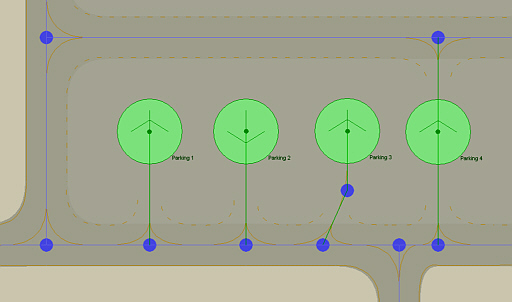
Arrange Parking Positions
Parking Spot Options
There are 4 safe Parking Spot Connector options:
- Parking = normal connector / spot heading N
- Parking = normal connector / spot heading S - (parking AI: nose S / arriving AI: nose N)
- Parking = connector with additional node / spot heading N
- Parking = connectors N and S / spot heading N - (AI uses both connectors / arriving AI: nose N or S )
Arrange Jetway Positions
Now I start to work down the Parking Specs entries which I've compiled earlier:
GATE WRRR Int  0 m43 ,255,255,255,CPA,GIA,JAA,JAL,TSO          Dummy = FSP B744 2nd cabin door
GATE WRRR Int -1 m41 ,255,255,255,CPA,SIA,THA                  Dummy = FSP B772 2nd cabin door
GATE WRRR Int -1 m40 ,255,255,255,CAL,GIA,JST,KAL,MAS,QTR      Dummy = PAI A332 2nd cabin door
GATE WRRR Flx  0 m35 ,235,235,235,EVA,JAL,LNI,THA,TSO,UIA,WON  Dummy = AIA B763 1st cabin door
GATE WRRR Flx -1 m23 ,235,235,235,COA,GIA,MAS,QFA,RBA          Dummy = AIA B738 1st cabin door
GATE WRRR Dom -1 m23 ,215,215,215,BTV,GIA,LNI,MDL              Dummy = AIA B738 1st cabin door
GATE WRRR Dom -2 m23 ,215,215,215,MNA,SJY                      Dummy = AIA B733 1st cabin door
- according to the AI Model Radiusing table, the first entry is for B747 (radius 43m) with Jetway Alignment Category "0"
- according to the Jetway Alignment Scheme, I have to take an FSP or PAI B747 (747fp) as Alignment Dummy
- I select an FSP B744 of an Airline with a very well visible 2nd cabin door (depends on paint scheme)
- I change to one of the two Top-Down View Options, activate the Slew Mode and select Slowest Simulation Rate
- I press F1 to force the dummy to sit down onto the apron
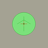
- now I slew the dummy with it's second cabin door to the Jetway Exit
- I press F1 to force the dummy to sit down onto the apron again and Pause the simulation
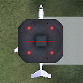
- in the AFCAD program I activate Lock The Map Location and deactivate it again
- now I position the parking spot in the AFCAD program with it's center exactly to the center of the red Crosshairs
- I do so with all remaining Parking Specs entries by using the appropriate dummies
- I use appropriate dummies also for the exclusive Airline Jetways, after I've worked down the parking specs entries list
Arrange Apron Positions
GATE WRRR Rmp  0 m23 ,155,155,155,AXM,VLU                      Dummy = B737
GATE WRRR Rmp  0 m16 ,155,155,155,ANOX,MNAX                    Dummy = Dash 8 Q400
- according to the AI Model Radiusing table, the first entry is for B737-Series (radius 23m)
- I select a B737 and change to one of the two Top-Down View Options,
activate the Slew Mode and select Slowest Simulation Rate
- I press F1 to force the dummy to sit down onto the apron
- now I slew the dummy to the Desired Position of the parking spot
- I press F1 to force the dummy to sit down onto the apron again and Pause the simulation
- in the AFCAD program I activate Lock The Map Location and deactivate it again
- now I position the parking spot in the AFCAD program with it's center exactly to the center of the red Crosshairs
- I do so with all remaining Parking Specs entries by using the appropriate dummies
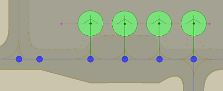
Separation Of Parking Positions
A proper Separation Of Parking Positions is critical to avoid wing overlappings and crashes.
- use the WingSpan column of the AI Model Radiusing table as reference for parking spot separation
- for Jetway Positions the jetway separation determins which models can park next to each other,
usually I test it with different dummies and make sure that no wing overlappings can occur
- for Apron Positions I use Dash 8 Q400 (Regional) / B757 (Gate Small) / B787 (Gate Medium) / A380 (Gate Heavy)
as dummies in order to achieve a safe parking spot separation
- consider Different Wingspans even of the same models which sometimes have different wing variations
- also consider that aircraft with Lower Radius Values can use the parking spot, too
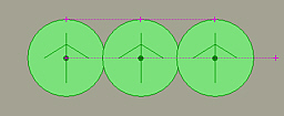
- make use of the Create Guidelines function in AFCAD program,
for aligning parking spots in a row and for a more easy separation by measuring distances with that function
I always use B763 (radius 35m) and B744 (radius 43m) as reference for grouping and compiling the Parking Specs entries, but more and more airlines switch to B787 and A380 with their greater wingspans. When I'm done with working down the parking specs entries for the Jetway Positions, I have no gates for B787 (radius 37m) and A380 (radius 45m). I therefore take a B787 Dummy, try out to which Gate Medium it would fit without striking neighboring parked aircraft, and change each the corresponding gate radius value from "35" to "37" meters. After that I take an A380 Dummy, try out to which Gate Heavy it would fit without striking neighboring parked aircraft, and change each the corresponding gate radius value from "43" to "45" meters.
Parking Connector
The parking spot must be connected to any taxiway by drawing a Parking Connector.
- the Parking Connector Heading must always match the spot heading
- the Parking Connector Surface must always match the apron surface type
- usually I set the Width to "80" ft, respectively to "40" ft for small GA and regional positions,
activate the Solid Center Line only, but no edge lines, and I uncheck all Lights
- parking connectors do have Blank designators, they remain unnamed
- also consider that aircraft with Lower Radius Values can use the parking spot, too
- make use of the Create Guidelines function in AFCAD program,
for aligning parking spots in a row and for a more easy separation by measuring distances with that function
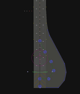
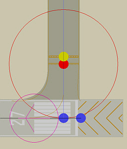
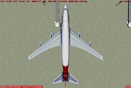
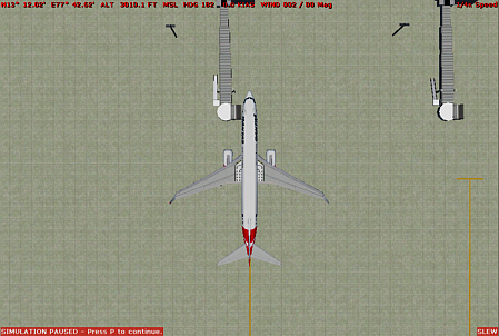
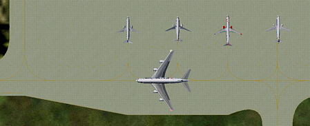
Make sure you consider the Aircraft Mainframe Length when placing a parking spot, no aircraft should have it's nose in any building, and no taxiing aircraft should strike a parked one. Also no aircraft should crash into ramplites or vehicles and the like.
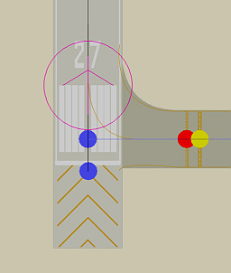
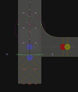
Both the images below show an easy trick to keep parking positions in a safe distance to the taxiway: I temporarly changed the width of the taxiway-segment to a safe 300ft, loaded the changes in FS, slewed a dummy B737 aircraft (the one with the red engines) with it's tail down to the dashed taxiway line, and set the parking position in AFCAD. As you can see, the A380 can taxi safely without striking the parked aircraft tail's. Of course, I changed the taxiway width back to it's original value after I had completed the parking position placement.
Parking Properties - Identification
- I name all Jetway positions Gate
- I name all Non-Jetway positions Parking
- I assign to all positions the correct Gate & Parking Number
Parking Properties - Type And Radius
- there are 10 Different Parking Types in FS9, they all must match particular radius values
- refer to AI Model Radiusing table for the correct radius value
- fill in the correct Radius (m) in meters, for example "43" for the first parking specs entry
Parking Properties - Parking Users
- get the Parking Specs entries from the Selection List drop down menu,
and the airline codes will be written automatically
- close the Parking Properties menu and the Parking Spot should now be colored,
and by clicking P repeatedly you can read it's naming and the assigned airline codes
Regionals / Cargo / GA / Overflow
There are some rules to follow, in order to avoid problems, since these parking positions could also be used as overflow positions for models with lower radius values. It is necessary to make sure that all possible models can use the spots without touching each other, without crashing into buildings, and without blocking taxiways.
- Overflow parking spots are positions for aircraft that won't use jetway and other specifically radiused
and airline-coded positions, they are always radiused according to the highest value of their corresponding parking type,
I use Dash 8 Q400 (Regional) / B757 (Gate Small) / B787 (Gate Medium) / A380 (Gate Heavy) as dummies,
I use the radius values "18" / "31" / "38" / "54" in meters, and I don't assign airline codes to overflow positions
- Regional aircraft and their parking spots can have 2 different radius values according to the AI Model Radiusing table,
I use Dash 8 Q400 as dummy, take the radius values "15" meters for regional jets and "16" meters for regional turboprops,
select Parking Type Gate Small if necessary, and assign airline codes to the positions
- Cargo aircraft and their parking spots can have 3 different radius values according to the AI Model Radiusing table,
I use Dash 8 Q400 (Cargo Aircraft Regional) / B757 (Cargo Aircraft Narrow Bodies) / A380 (Cargo Aircraft Wide Bodies)
as dummies, take the radius values "17" / "30" / "50" in meters, select Parking Type Ramp Cargo,
and sometimes assign airline codes to cargo positions
- Maintenance parking spots are normally situated next to hangars of particular airlines, I give to them the proper airline code
and radius value, and I use corresponding aircraft of that particular airline as dummies for positioning the parking spot
- General Aviaton parking spots will be coded with string BBJ0,G000,G001,G002,G003,G004,G005,G006,G007,G008
and radiused with "18" meters, I select Parking Type GA Large
- Boeing Business Jets parking spots will be coded with string BBJ0,G000,G001,G002,G003,G004,G005,G006,G007,G008
and radiused with "29" meters, I select Parking Type GA Large
Tower Viewpoint
Often a Tower Viewpoint is missing, just add it at the correct location:
- in the AFCAD program create a Tower Viewpoint, copy and paste the coordinates from any other object for example
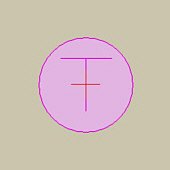
- in FS change to Top-Down View and slew a small dummy aircraft to the center of the Tower Position in the scenery
- press F1 to force the dummy to sit down and Pause the simulation
- in the AFCAD program activate Lock The Map Location and deactivate it again
- move the tower viewpoint in the AFCAD program with it's center exactly to the center of the red Crosshairs
- the Elevation (ft ASL) of the tower windows adds to the airport altitude
Final Checks
While designing an AFCAD many Errors Can Creep In, also some sections of AFCADs have nothing to do with 'designing', but possibly with correcting data. I therefore take some time to check everything, after I have completed my work on an AFCAD:
- run the Fault Finder and correct every possible error
- check whether there is a Tower Viewpoint with proper altitude at the correct position
- check that all Start Locations are correct with regard to position / heading / designator / start type
- check all ILS Hold Short Nodes to be inserted properly
- make sure you have corrected all Runways / Taxiways / Aprons and that Closed Taxiways are interrupted
- make sure you have improved runways by adding Runway U-Turns if applicable
- make sure you have improved taxiways by adding Runway & Taxiway V-Turns
- check all Parking Spots to have sufficient space to neighbouring spots, taxiways, jetways, buildings and other objects
- check all Parking Spot Connector headings to match their parking spot headings
- in the Parking List tab "Radius", check all radius values to match each their "Parking Type"
according to the AI Model Radiusing table;
Gate Small must be radiused with anything between "21" and "31" meters, respectively "15" or "16" or "19" meters
Gate Medium must be radiused with anything between "32" and "38" meters
Gate Heavy must be radiused with anything between "39" and "54" meters
Ramp GA Small must be radiused with "6" or "8" or "10" meters
Ramp GA Medium must be radiused with "14" meters
Ramp GA Large must be radiused with "18" meters
Ramp Cargo must be radiused with "17" or "29" or "30" or "37" or "50" meters
- in the Parking List tab "Parking Codes", check that everything is correct, and that all Parking Specs
entries as well as Exclusive Airline Parking Spots / GA Parking Codes / Cargo Parking Spots are coded properly
- in the Parking List tab "Area", make sure that the Gate & Parking Numbering is correct
- click Ctrl + T repeatedly and check whether every single Blank / Taxiway / Runway designator is correct
- take a look to the Comm Frequencies List, compare the data with real world data if available, and correct possible errors
- take a look to the Navaids List, compare the data with real world data if available, and correct possible errors
- click L and make sure that the Night Lighting is correct
- run the Fault Finder again for a last time
How To Create An Exclude File
Preparations
- go to 'MICROSOFT GAMES\Flight Simulator 9\Addon Scenery' and create subfolder 'Temp'
- go to 'MICROSOFT GAMES\Flight Simulator 9\Addon Scenery\Temp' and create subfolder 'scenery'
- go to 'MICROSOFT GAMES\Flight Simulator 9\Addon Scenery\Temp' and create subfolder 'engineering'
- install scenery 'Temp' in the FS Scenery Library - refer to Scenery & AFCAD Troubleshooting if necessary
Downloads
- download and install MSXML 4.0 Service Pack 2 if you don't already have it installed
(select other system language version if necessary)
- download and install FS2004 SDK BGLComp2 from the Flight Simulator 9 SDK page
- move files bglcomp.exe and bglcomp.xsd from folder FS2004SDK\BGLCOMP_SDK
to folder MICROSOFT GAMES\Flight Simulator 9\Addon Scenery\Temp\engineering
- download ExcBuilder Version 2.0
- extract file ExcBuilderV2.exe to
MICROSOFT GAMES\Flight Simulator 9\Addon Scenery\Temp\engineering
- download FSConnect 3.00
- extract file FSConnect.dll to
MICROSOFT GAMES\Flight Simulator 9\Modules
Create An Exclude File
In this example the famous autogen palms on KLAX Los Angeles taxiway Q1 of the default scenery will be excluded.
They may be already excluded by any addon sceneries you have installed, btw.
- open ExcBuilderV2 and define location of bglcomp.exe in the settings menu
- open AFCAD and airport KLAX
- open FS2004 and select Autogen density: Extremely dense in the Display Settings
- in FS2004 select a small user aircraft (for example Lear 45)
- in FS2004 or AFCAD go to KLAX and slew your user aircraft to the palms on taxiway Q1
- make sure your aircraft's nose faces north in Top-down view
- in FS2004 slew to a northwestern position close to the pamls and pause the simulation
- in ExcBuilderV2 Exclusion area - Northwest point click Lat: FSC and click Lon: FSC to fill in the fields
- in FS2004 slew to a southeastern position close to the pamls and pause the simulation
- in ExcBuilderV2 Exclusion area - Southeast point click Lat: FSC and click Lon: FSC to fill in the fields
- select Exclusion type in this case All Objects
- uncheck Delete source after compilation?
- click Generate source code
- click Save source and generate .bgl
- name your exclusion file klax-palms-twy-q1-exclude
- if no klax-palms-twy-q1-exclude.BGL file appears in folder
MICROSOFT GAMES\Flight Simulator 9\Addon Scenery\Temp\engineering
just open file klax-palms-twy-q1-exclude.xml with a text editor
and make sure that all lat and log values contain a point and not a comma
drag file klax-palms-twy-q1-exclude.xml onto bglcomp.exe
- copy file klax-palms-twy-q1-exclude.BGL to folder
MICROSOFT GAMES\Flight Simulator 9\Addon Scenery\Temp\scenery
- open FS2004 and look for the palms to be vanished
Attention
- It is very important to know, that objects are grouped sometimes, especially at smaller airports.
Therefore it is not always possible to exclude single objects at particular airports for example,
sometimes not even single buildings or trees.
- Try to avoid moving an exclude area over the AFCAD Airport Reference Point,
it may exclude the AFCAD in some cases !
Create A Single Exclude File With More Than One Exclusion Area
- create an exclude file with program ExcBuilderV2 as describe above in section Create An Exclude File
- collect Exclusion Area data with program ExcBuilderV2 for another object
- click Generate Source Code
- copy and paste the ExclusionRectangle tag to the Exclude XML File
An exclude file code with 3 exclusion areas would look like this one :
<?xml version="1.0" encoding="ISO-8859-1"?>
<FSData version="9.0"
xmlns:xsi='http://www.w3.org/2001/XMLSchema-instance'
xsi:noNamespaceSchemaLocation="bglcomp.xsd">
<ExclusionRectangle
latitudeMinimum = "33.9404873569176"
latitudeMaximum = "33.9407551710025"
longitudeMinimum = "-118.412039969017"
longitudeMaximum = "-118.411621375461"
excludeAllObjects = "TRUE"/>
<ExclusionRectangle
latitudeMinimum = "33.9428097463948"
latitudeMaximum = "33.9437336650647"
longitudeMinimum = "-118.41836796552"
longitudeMaximum = "-118.416866007723"
excludeAllObjects = "TRUE"/>
<ExclusionRectangle
latitudeMinimum = "33.9398557068764"
latitudeMaximum = "33.9413095572424"
longitudeMinimum = "-118.416815679599"
longitudeMaximum = "-118.415041563576"
excludeAllObjects = "TRUE"/>
</FSData>
How To Remove And Reinstate Taxiway Signs
Downloads
- download New Bgl Analyze and extract file NewBglAnalyze.exe to
MICROSOFT GAMES\Flight Simulator 9\Addon Scenery\Temp\engineering
- optionally download and install Create Sign - Program For Taxiway Sign Creation
Remove And Reinstate Taxiway Signs
In this example all KLAX Los Angeles taxiway signs will be excluded and reinstated,
in which particular signs can be left out, and or new created signs be added to the scenery.
- create an exclude file with program ExcBuilderV2 as describe above in section
Create An Exclude File by laying an Exclusion Area over the entire airport and activating
Exclusion Type Taxiway Signs only
- compile and install the Taxiway Sign Exclude File to FS2004
- open FS2004 and look for the taxiway signs to be vanished
- open AFCAD and stock airport AFCAD file for KLAX and click Open Airport once again
- check From Specific File and click Open File and copy file name AP916190.BGL
- in folder MICROSOFT GAMES\Flight Simulator 9\Scenery do a search for file AP916190.BGL
- copy file AP916190.BGL to folder
MICROSOFT GAMES\Flight Simulator 9\Addon Scenery\Temp\engineering
- open program NewBglAnalyze and open file AP916190.BGL
- click Disassemble to XML and file AP916190.txt will be created
- in folder MICROSOFT GAMES\Flight Simulator 9\Addon Scenery\Temp\engineering
create an emtpy text file and name it klax-twy-signs.txt
- open file klax-twy-signs.txt in WordPad and paste the following code to the file :
<?xml version="1.0" encoding="ISO-8859-1"?>
<FSData version="9.0"
xmlns:xsi='http://www.w3.org/2001/XMLSchema-instance'
xsi:noNamespaceSchemaLocation="bglcomp.xsd">
- AIRPORT HEADER -
- TAXIWAY SIGN ENTRIES -
</Airport>
</FSData>
- open file AP916190.txt in WordPad and do a search for entry Airport ident="KLAX"
- mark the Airport Header
<Airport ident="KLAX"
region=""
country="United States"
state="California"
city="Los Angeles"
name="Los Angeles Intl"
lat="N33 56.55218"
lon="W118 24.48450"
alt="38.40M"
magvar="346.10">
- copy and paste Airport Header code to file klax-twy-signs.txt replacing - AIRPORT HEADER -
- from the Airport Header entry position in file AP916190.txt do a search for entry TaxiwaySign
- begin to mark all TaxiwaySign entries down to the Services entry that follows them usually
- copy and paste all TaxiwaySign entries to klax-twy-signs.txt replacing - TAXIWAY SIGN ENTRIES -
- invert justification of every TaxiwaySign entry by renaming justification="LEFT" to justification="R"
and justification="RIGHT" to justification="LEFT" and finally justification="R" to justification="RIGHT"
- locate and remove undesired or move misplaced or add new created TaxiwaySigns at this point
- close file klax-twy-signs.txt and rename it klax-twy-signs.xml
- drag file klax-twy-signs.xml onto bglcomp.exe
- copy new created file klax-twy-signs.BGL to folder
MICROSOFT GAMES\Flight Simulator 9\Addon Scenery\Temp\scenery
- open FS2004 and look for the taxiway signs to be reinstated and justificated correctly
Taxiway Sign Codes
The 3 Different Types Of Taxiway Signs
- location sign - yellow lettering on black background - code : l
- direction sign - black lettering on yellow background - code : d
- runway sign - white lettering on red background - code : m
Location Signs
- location sign for taxiway AF - code : l[AF]
- location sign for taxiway N1 - code : l[N1]
Runway Signs
- runway sign for runway 9-27 - code : m[9-27]
- runway sign for runway 09R-27L - code : m[09R-27L]
Direction Signs
| | Direction | Character | Code |
| | straight ahead | caret | ^ |
| | left | less than symbol | < |
| | right | greater than symbol | > |
| | ahead and right | left quote | ` |
| | ahead and left | apostrophe | ' |
| | back and left | forward slash | / |
| | back and right | backslash | \ |
Taxiway Sign Entries Attributes
- label required / 6 characters maximum to be displayed on sign
- justification optional - code : LEFT or RIGHT
- size required - code : SIZE1 to SIZE5
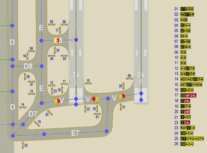
Sample Taxiway Sign Codes
| Number |
Sign
| Code |
Number |
Sign
| Code |
| 01 |

| l[E7]d<V> |
14 |

| d/D7|<E7l[D]dD7> |
| 02 |

| d`El[D7]dV' |
15 |

| d/E7l[D7]dD7'|D\ |
| 03 |

| d<E8 |
16 |

| l[D8]d<E> |
| 04 |

| l[E]dE8> |
17 |

| l[E8]m6R-24L |
| 05 |

| l[E]d<E8 |
18 |

| l[V]m24L |
| 06 |

| dE8> |
19 |

| l[V]dE7> |
| 07 |

| l[E]d<D8 |
20 |

| l[V]m24R |
| 08 |

| l[E]dD8> |
21 |

| l[V]d<E7 |
| 09 |

| dV> |
22 |

| l[V]m24L |
| 10 |

| d<V |
23 |

| d`D7l[V]dE> |
| 11 |

| dV> |
24 |

| l[E8]d<E> |
| 12 |

| d<Vl[E]dD7' |
25 |

| l[E7]dD7^|D>|D7\ |
| 13 |

| d<Vl[E]dD7' |
26 |

| l[D8]d<D> |
Taxiway Sign Layout
Sample Taxiway Sign Layout
|
